
Building a 360° product turntable with 3D printing and Arduino
A slow, smooth turntable with a speed knob and a direction button. CAD design, parts list, wiring diagram and Arduino code so you can build your own.
Published
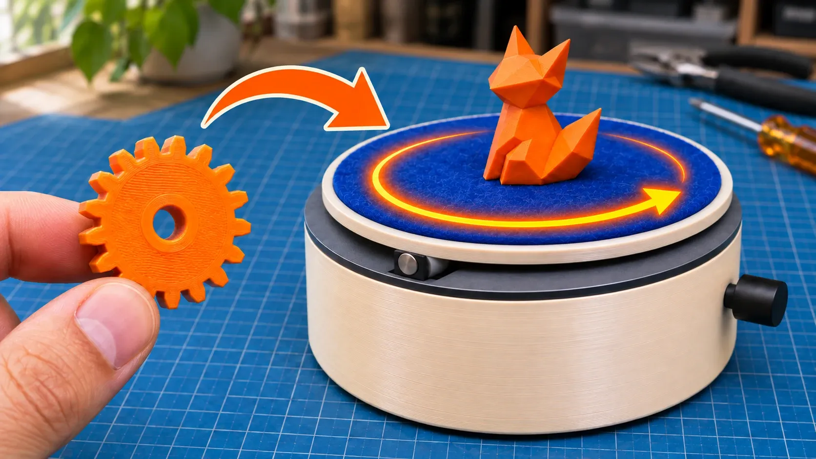
The first FoxBench DIY machine is a product turntable: a round platter that turns slowly and evenly, for filming products in 360° on a backdrop. It will also be the most reused machine on the channel, because every machine built after it will stand on this platter for its final shot.
The goals from the start:
- Turn slowly and smoothly, with no jitter, so the footage stays clean.
- Adjustable speed with a knob, reverse direction with a button.
- Carry around 1kg without the platter sagging.
- Run from an ordinary USB-C cable.
- Use bearings, shafts and screws already on the workshop shelf.
Work in progress: the design is done and test prints and the circuit are being checked. This post will be updated with photos of the real machine and the video once it is filmed.
CAD design
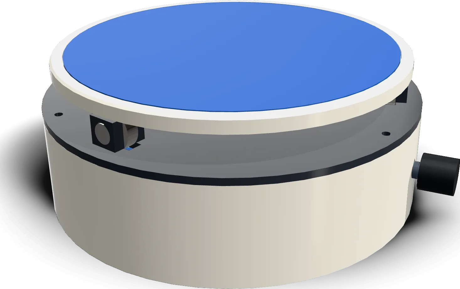
Overall size is Ø160 × 64.5mm, made of 6 printed parts. Every part is already oriented for printing without supports.
| Part | Size | Notes |
|---|---|---|
| Base | Ø160 × 42mm | Holds the Arduino Nano, ULN2003 board and switch. Knob and button holes at the front, USB opening at the back |
| Top plate | 3mm thick | Center bearing boss, 3 roller blocks, motor mounted from below |
| Platter | Ø150 × 6mm | 1mm recess on top for felt, Ø8 stainless shaft pressed through the center |
| Ring gear | 75 teeth, module 1.2 | Screwed under the platter with 4 M3 screws into brass inserts |
| Pinion | 15 teeth | D-shaped bore, press fit on the motor shaft |
| Push button | — | Goes through the base wall and presses the switch lever inside |
1:5 gear drive
A 28BYJ-48 stepper drives the 15-tooth pinion, which meshes with the 75-tooth ring gear under the platter. The 15:75 = 1:5 ratio slows the platter down and multiplies torque. The motor tops out at about 12 rpm, so the platter’s top speed is about 2.3 rpm, roughly 26 seconds per turn: slow enough for product shots.
The gears use +0.25 / −0.25 profile shift and about 0.14mm of backlash, so printed gears run smoothly without binding.
Platter on three rollers
Instead of hanging the whole platter on the center bearing, the platter rides on three 688 bearings used as rollers at a 66mm radius, close to the wall. The center bearing only keeps the platter centered. Two benefits:
- The load goes down near the wall, so the 3mm top plate does not flex under a heavy object.
- The platter lifts straight off for cleaning or replacing the felt.
Print colors
Printed in PLA. The body is a light color to stand out against the blue backdrop, the gears are dark, and the button is a bright color (red or orange) so it reads well on camera.
Parts list
Mechanical (mostly common 3D-printing workshop stock):
| Item | Qty | Used for |
|---|---|---|
| 688 bearing (8×16×5mm) | 4 | 1 center + 3 rollers |
| Ø8 stainless rod | 1 × 18.5mm + 3 × 14.6mm | Center shaft (pressed into platter) + roller axles |
| Ø2 steel pin | 2 × 14mm | Pins holding the limit switch |
| Brass heat-set insert M3×6×4.5 | 4 | Ring gear |
| Brass heat-set insert M3×4×4.5 | 3 | Lid posts in the base |
| M3×6 screw | 8 | Ring gear and ULN2003 board |
| M3×10 screw + M3 nut | 5 screws, 2 nuts | Lid to base, motor mount |
| Adhesive felt (or rubber sheet) | 1 × Ø140mm | Platter surface |
Electronics:
| Item | What to look for |
|---|---|
| 28BYJ-48 stepper | The 5V version |
| ULN2003 driver board | The one sold with the 28BYJ-48 |
| Arduino Nano | USB-C, headers not soldered (fits better) |
| Potentiometer | B10K, M7 threaded neck, Ø6 shaft |
| Knob | Fits a Ø6 shaft |
| KW11 limit switch | 16mm lever, used as the direction button |
| Wire, heat shrink | 24–26AWG |
| USB-C cable + 5V charger | Any phone charger |
Wiring
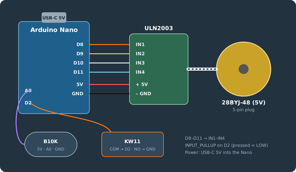
| Arduino Nano | Connects to |
|---|---|
| D8, D9, D10, D11 | IN1, IN2, IN3, IN4 on the ULN2003 board |
| 5V, GND | + and − on the ULN2003 board |
| A0 | Potentiometer wiper (outer pins to 5V and GND) |
| D2 | KW11 switch: COM to D2, NO to GND |
The whole machine runs from one USB-C cable into the Nano. The 5V 28BYJ-48 draws very little current, so USB power is enough, with no separate supply.
Arduino code
The sketch uses the AccelStepper library (in the Arduino IDE: Sketch → Include Library → Manage Libraries, search for “AccelStepper”). The knob sets the speed from 0 to 800 steps per second, and each button press reverses the platter.
#include <AccelStepper.h>

// Pin order 8, 10, 9, 11 is correct for the 28BYJ-48
AccelStepper motor(AccelStepper::HALF4WIRE, 8, 10, 9, 11);
const int POT = A0;
const int BTN = 2;
int dir = 1;
bool lastBtn = HIGH;

void setup() {
  pinMode(BTN, INPUT_PULLUP);
  motor.setMaxSpeed(1000);
}

void loop() {
  bool b = digitalRead(BTN);
  if (lastBtn == HIGH && b == LOW) {  // button pressed: reverse
    dir = -dir;
    delay(30);                         // debounce
  }
  lastBtn = b;

  int speed = map(analogRead(POT), 0, 1023, 0, 800);  // steps per second
  motor.setSpeed(dir * speed);
  motor.runSpeed();
}
Two easy mistakes:
- The 8, 10, 9, 11 pin order in the motor declaration is on purpose. With 8, 9, 10, 11 the 28BYJ-48 just buzzes in place instead of turning.
- The button uses
INPUT_PULLUP, so no external resistor is needed: D2 reads HIGH normally and LOW when the button connects it to GND.
The code has not yet been tested on the finished machine. Run the circuit on a breadboard before fitting it into the base.
Assembly
- Print the 6 parts plus a tolerance test piece. Print the gear pair first to check the mesh.
- Cut the Ø8 stainless rod with a cut-off wheel: one 18.5mm piece and three 14.6mm pieces, then grind the ends flat.
- Install the M3 brass inserts with a soldering iron into the ring gear and the 3 posts in the base.
- Press the 688 bearing into the top plate’s center boss, and press the Ø8 shaft into the platter.
- Fit the 3 rollers: drop each bearing into its slot and tap the steel axle through the block.
- Solder wires to the potentiometer and switch, connect Nano – ULN2003 – motor, upload the code and test the motor on the bench.
- Mount the motor under the top plate and push the pinion onto its shaft.
- Fit the electronics into the base, insert the two Ø2 pins for the switch, drop the button into its hole and tidy the wires.
- Screw the ring gear under the platter with 4 M3×6 screws and stick the felt on top.
- Drop the platter in: the shaft goes into the bearing, the platter rests on the 3 rollers and the gears mesh. Fix the top plate to the base with 3 screws.
Printing and tolerance tips
Every printer makes holes a little bigger or smaller. Before printing the full set, print a small test block to tune three key sizes:
- Ø8 shaft holes: about Ø8.2–8.3 for a sliding fit, Ø7.9–8.0 for a press fit.
- 688 bearing pocket: about Ø16.1 for a hand press fit.
- M3 insert holes: about Ø4.0.
The STL pack will include this tolerance test piece.
Coming next
Once the machine is running, this post will get photos, the YouTube video and a load test with about 1kg on the platter. The next build is a heat-set insert press, used to install the brass inserts for this turntable and every machine after it.